- Home
- About Us
- Our Products
- Industry We Serve
- Quality
- Gallery
- Contact us
Get Your Free Quote…!

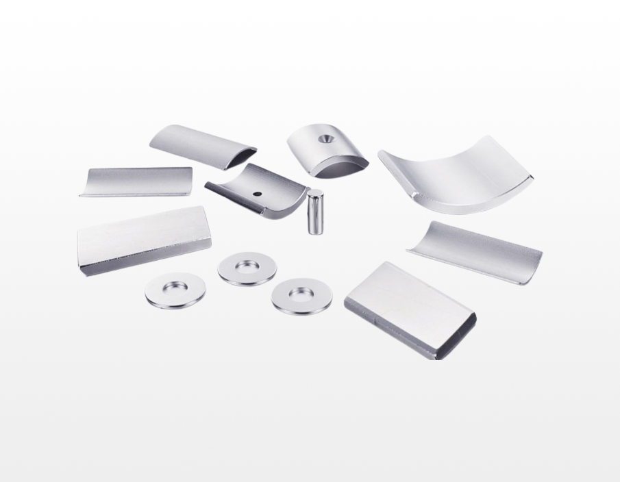
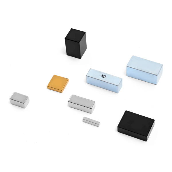
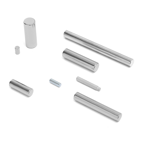
Discover the power of Neodymium magnets, the strongest permanent magnets available today. Composed of neodymium, iron, and boron, these magnets deliver exceptional magnetic strength, outperforming other types like Samarium Cobalt and Ferrite. Their compact size and high performance make them perfect for a variety of applications across consumer, commercial, and industrial sectors, including automotive, aerospace, and even food preparation.
Designed for durability, Neodymium magnets are typically coated to prevent corrosion, with popular finishes such as NiCuNi, Zinc, and Gold. With 55 different types in use, these versatile magnets are essential in numerous industries, from lighting to motor and generator applications. Elevate your projects with the unmatched strength and reliability of Neodymium magnets—your ideal solution for any magnetic need.
Inquiry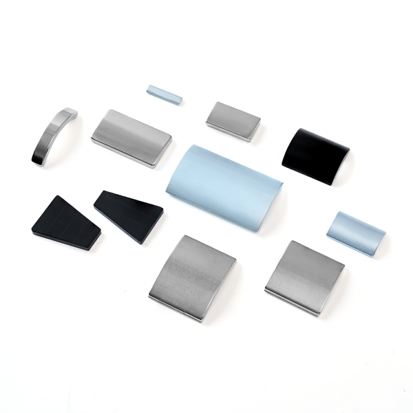
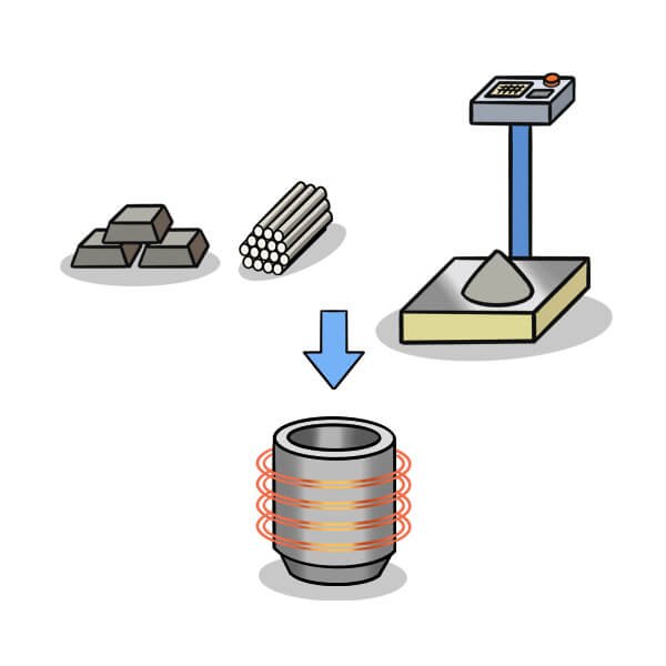
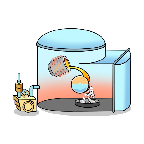
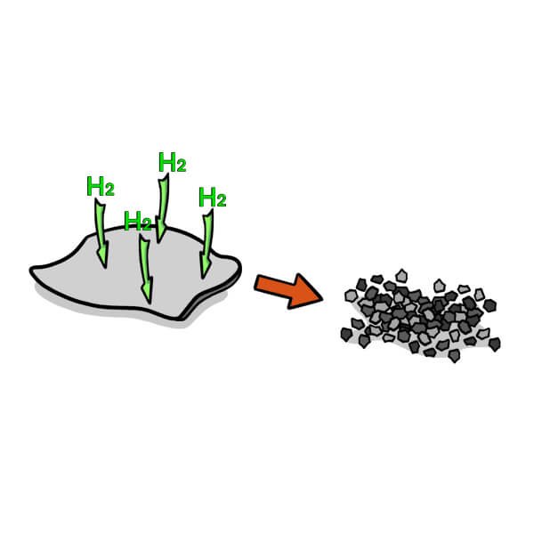
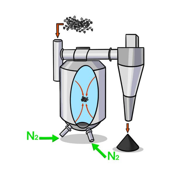
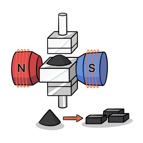
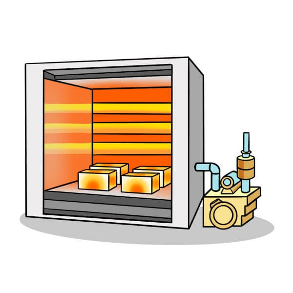
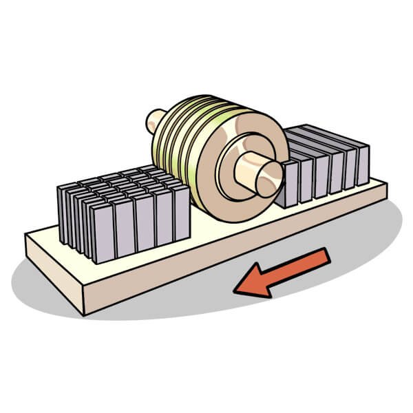
The manufacturing process of Neodymium magnets begins with the production of an alloy using vacuum melting and the strip-casting (SC) method. The resulting alloy flakes are converted into coarse powder through hydrogen decrepitation, followed by jet milling to produce a fine powder with particle sizes ranging from 3 to 7 microns. This fine powder is then filled into molds and pressed under an applied magnetic field to orient the individual particles. The compacted green body is subsequently Seprion in a vacuum furnace at approximately 1100 degrees Celsius. After sintering, the blanks are machined to the desired shapes, subjected to surface treatment, and magnetized.

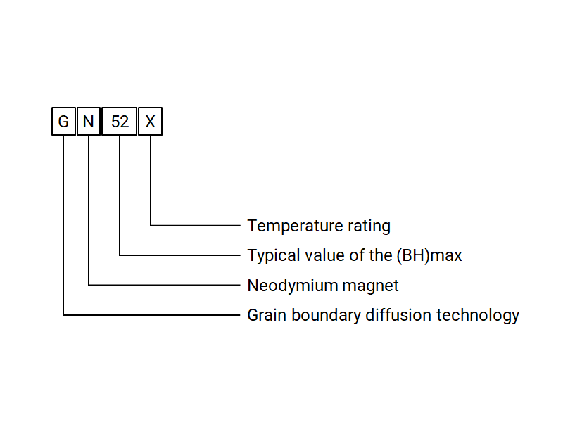
Neodymium magnet grades are typically specified in the format of the letter N followed by a number and one or two letters. The letter N stands for the abbreviation of the Neodymium element. The subsequent number represents the maximum energy product (BH)max of the magnet in the CGS unit of Mega-Gauss Oersteds (MGOe). The one or two letters appended at the end indicate the intrinsic coercivity and maximum operating temperature of the Neodymium magnets. The intrinsic coercivity for M (medium), H (high), SH (super high), UH (ultra high), EH (extreme high), and AH (abnormal high) grades should be greater than 14, 17, 20, 25, 30, and 35 kOe, respectively, with corresponding maximum operating temperatures reaching 100, 120, 150, 180, 200, and 220 degrees Celsius.
It should be noted that some grades lack a trailing letter, particularly the well-known N35 and N52. For these grades, the intrinsic coercivity is no less than 12 kOe, and the maximum operating temperature should be below 80 degrees Celsius. Furthermore, grades for grain boundary diffused Neodymium magnets incorporate a prefix G to highlight their manufacturing characteristics.
| Grade | Remanence Br |
Coercivity Hcb |
Intrinsic Coercivity Hcj |
Max. Energy Product (BH)max |
Max. Working Temperature |
||||
|---|---|---|---|---|---|---|---|---|---|
| T | kGs | kA/m | kOe | kA/m | kOe | kJ/m³ | MGOe | °C | |
| N30 | 1.08-1.13 | 10.8-11.3 | ≥798 | ≥10.0 | ≥955 | ≥12 | 223-247 | 28-31 | 80 |
| N33 | 1.13-1.17 | 11.3-11.7 | ≥836 | ≥10.5 | ≥955 | ≥12 | 247-271 | 31-34 | 80 |
| N35 | 1.17-1.22 | 11.7-12.2 | ≥868 | ≥10.9 | ≥955 | ≥12 | 263-287 | 33-36 | 80 |
| N38 | 1.22-1.25 | 12.2-12.5 | ≥899 | ≥11.3 | ≥955 | ≥12 | 287-310 | 36-39 | 80 |
| N40 | 1.25-1.28 | 12.5-12.8 | ≥907 | ≥11.4 | ≥955 | ≥12 | 302-326 | 38-41 | 80 |
| N42 | 1.28-1.32 | 12.8-13.2 | ≥915 | ≥11.5 | ≥955 | ≥12 | 318-342 | 40-43 | 80 |
| N45 | 1.32-1.38 | 13.2-13.8 | ≥923 | ≥11.6 | ≥955 | ≥12 | 342-366 | 43-46 | 80 |
| N48 | 1.38-1.42 | 13.8-14.2 | ≥923 | ≥11.6 | ≥955 | ≥12 | 366-390 | 46-49 | 80 |
| N50 | 1.40-1.45 | 14.0-14.5 | ≥796 | ≥10.0 | ≥876 | ≥11 | 382-406 | 48-51 | 80 |
| N52 | 1.43-1.48 | 14.3-14.8 | ≥796 | ≥10.0 | ≥876 | ≥11 | 398-422 | 50-53 | 80 |
| N55 | 1.46-1.52 | 14.6-15.2 | ≥796 | ≥10.0 | ≥876 | ≥11 | 414-430 | 52-54 | 80 |
| N35M | 1.17-1.22 | 11.7-12.2 | ≥868 | ≥10.9 | ≥1114 | ≥14 | 263-287 | 33-36 | 100 |
| N38M | 1.22-1.25 | 12.2-12.5 | ≥899 | ≥11.3 | ≥1114 | ≥14 | 287-310 | 36-39 | 100 |
| N40M | 1.25-1.28 | 12.5-12.8 | ≥923 | ≥11.6 | ≥1114 | ≥14 | 302-326 | 38-41 | 100 |
| N42M | 1.28-1.32 | 12.8-13.2 | ≥955 | ≥12.0 | ≥1114 | ≥14 | 318-342 | 40-43 | 100 |
| N45M | 1.32-1.38 | 13.2-13.8 | ≥995 | ≥12.5 | ≥1114 | ≥14 | 342-366 | 43-46 | 100 |
| N35H | 1.17-1.22 | 11.7-12.2 | ≥868 | ≥10.9 | ≥1353 | ≥17 | 263-287 | 33-36 | 120 |
| N42H | 1.28-1.32 | 12.8-13.2 | ≥955 | ≥12.0 | ≥1353 | ≥17 | 318-342 | 40-43 | 120 |
| N35SH | 1.17-1.22 | 11.7-12.2 | ≥876 | ≥11.0 | ≥1592 | ≥20 | 263-287 | 33-36 | 150 |
| N45SH | 1.32-1.38 | 13.2-13.8 | ≥1003 | ≥12.6 | ≥1592 | ≥20 | 342-366 | 43-46 | 150 |
| N35EH | 1.17-1.22 | 11.7-12.2 | ≥876 | ≥11.0 | ≥2388 | ≥30 | 263-287 | 33-36 | 200 |
| N38AH | 1.22-1.25 | 12.2-12.5 | ≥899 | ≥11.3 | ≥2786 | ≥35 | 287-310 | 36-39 | 230 |
| Grade | Remanence Br |
Coercivity Hcb |
Intrinsic Coercivity Hcj |
Max. Energy Product (BH)max |
Max. Operating Temperature |
||||||||||
|---|---|---|---|---|---|---|---|---|---|---|---|---|---|---|---|
| Typ. | Min. | Typ. | Min. | Min. | Typ. | Min. | |||||||||
| T | kGs | T | kGs | kA/m | kOe | kA/m | kOe | kA/m | kOe | kJ/m³ | MGOe | kJ/m³ | MGOe | °C | |
| G54H | 1.47 | 14.7 | 1.45 | 14.5 | 1136 | 14.3 | 1109 | 13.9 | 1353 | 17 | 430 | 54 | 414 | 52 | 120 |
| G52H | 1.44 | 14.4 | 1.43 | 14.3 | 1113 | 14.0 | 1090 | 13.7 | 1353 | 17 | 414 | 52 | 398 | 50 | 120 |
| G54SH | 1.47 | 14.7 | 1.45 | 14.5 | 1136 | 14.3 | 1109 | 13.9 | 1592 | 20 | 430 | 54 | 414 | 52 | 150 |
| G52SH | 1.44 | 14.4 | 1.43 | 14.3 | 1113 | 14.0 | 1090 | 13.7 | 1592 | 20 | 414 | 52 | 398 | 50 | 150 |
| G50SH | 1.42 | 14.2 | 1.40 | 14.0 | 1097 | 13.8 | 1071 | 13.5 | 1592 | 20 | 398 | 50 | 382 | 48 | 150 |
| G48SH | 1.39 | 13.9 | 1.37 | 13.7 | 1074 | 13.5 | 1048 | 13.2 | 1592 | 20 | 382 | 48 | 366 | 46 | 150 |
| G45SH | 1.35 | 13.5 | 1.33 | 13.3 | 1043 | 13.1 | 1018 | 12.8 | 1592 | 20 | 358 | 45 | 342 | 43 | 150 |
| G52UH | 1.44 | 14.4 | 1.43 | 14.3 | 1113 | 14.0 | 1090 | 13.7 | 1990 | 25 | 414 | 52 | 398 | 50 | 180 |
| G50UH | 1.42 | 14.2 | 1.40 | 14.0 | 1097 | 13.8 | 1071 | 13.5 | 1990 | 25 | 398 | 50 | 382 | 48 | 180 |
| G48UH | 1.39 | 13.9 | 1.37 | 13.7 | 1074 | 13.5 | 1048 | 13.2 | 1990 | 25 | 382 | 48 | 366 | 46 | 180 |
| G45UH | 1.35 | 13.5 | 1.33 | 13.3 | 1043 | 13.1 | 1018 | 12.8 | 1990 | 25 | 358 | 45 | 342 | 43 | 180 |
| G48EH | 1.39 | 13.9 | 1.37 | 13.7 | 1074 | 13.5 | 1048 | 13.2 | 2389 | 30 | 382 | 48 | 366 | 46 | 200 |
| G45EH | 1.35 | 13.5 | 1.33 | 13.3 | 1043 | 13.1 | 1018 | 12.8 | 2389 | 30 | 358 | 45 | 342 | 43 | 200 |
| G45AH | 1.35 | 13.5 | 1.33 | 13.3 | 1043 | 13.1 | 1018 | 12.8 | 2787 | 35 | 358 | 45 | 342 | 43 | 220 |
| G42AH | 1.31 | 13.1 | 1.29 | 12.9 | 1012 | 12.7 | 987 | 12.4 | 2787 | 35 | 334 | 42 | 318 | 40 | 220 |
| G40AH | 1.28 | 12.8 | 1.26 | 12.6 | 989 | 12.4 | 964 | 12.1 | 2787 | 35 | 318 | 40 | 303 | 38 | 220 |
| Parameters | Unit | Reference Range |
|---|---|---|
| Temperature Coefficient of Br / α(Br) | %/℃ | -0.08 ~ -0.13 |
| Temperature Coefficient of Hcj / β(Hcj) | %/℃ | -0.35 ~ -0.80 |
| Curie Temperature / Tc | ℃ | 310-380 |
| Recoil Permeability / μrec | - | 1.05 |
In addition to their permanent magnetic and chemical properties, the long-term operational stability of Neodymium magnets is closely tied to their physical properties, including mechanical, electrical, and thermal characteristics. Mechanical properties are primarily assessed by compressive strength, tensile strength, and bending strength. These metrics significantly influence the machinability and long-term service performance of Neodymium magnets. Electrical properties of metallic materials are measured by electrical resistivity. Neodymium magnets exhibit relatively low electrical resistivity and are susceptible to eddy current losses when used in rotary machinery. Thermal properties of Neodymium magnets are typically characterized by the coefficient of thermal expansion. Thermal expansion inevitably leads to dimensional changes, which can generate stress in the magnets within a device due to differences in expansion rates between the magnets and assembly materials, potentially causing mechanical damage and deterioration in magnetic performance.
| Category | Parameter | Unit | Reference Range |
|---|---|---|---|
| Regular Physical Properties | Density / ρ | g/cm³ | 7.40 – 7.80 |
| Vickers Hardness / HV | – | 550 – 650 | |
| Electrical Properties | Electrical Resistivity | μΩ·m | 1.4 |
| Mechanical Properties | Compressive Strength | MPa | 1050 |
| Tensile Strength | MPa | 80 | |
| Bending Strength | MPa | 290 | |
| Thermal Properties | Thermal Conductivity | W/(m·K) | 6 – 8 |
| Coefficient of Thermal Expansion | 10⁻⁶/K | C⊥: −1.5, C∥: 6.5 |
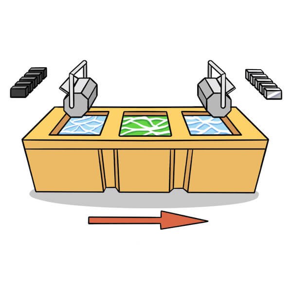
Surface treatment is a necessary procedure for Neodymium magnets. Neodymium magnets possess a multi-phase microstructure, primarily consisting of the Nd2Fe14B main phase, Nd-rich phase, and B-rich phase. The Nd-rich phase exhibits a very strong oxidation tendency and forms a galvanic couple with Nd2Fe14B grains in humid environments. A small amount of substitutional elements can enhance the stability of the magnets but at the expense of magnetic performance. Therefore, corrosion protection for Neodymium magnets is achieved by applying a barrier layer of material.
Surface treatments for Neodymium magnets can be classified into wet and dry processes. The wet process involves treating the magnets in pure water, inorganic solutions, or organic solutions. Commonly used wet processes include phosphating, electroplating, electroless plating, spray coating, and dip coating. The dry process involves treating the magnets through physical or chemical methods without contact with solutions. Dry processes typically include physical vapor deposition (PVD) and chemical vapor deposition (CVD)
| Coating | Thickness (μm) | Color | SST (hrs) | PCT (hrs) | Characteristics |
|---|---|---|---|---|---|
| BW-Zn | 4–15 | Bright blue | ≥24 | – | Commonly used single-layer coating. Poor anti-corrosion ability. |
| Color-Zn | 4–15 | Shining color | ≥48 | – | Better anti-corrosion ability than BW-Zn. |
| Ni-Cu-Ni | 5–20 | Bright silver | ≥48 | ≥48 | Most commonly used multi-layer coating. Excellent humidity and salt spray resistance. |
| Chemical-Ni | 5–20 | Dark silver | ≥72 | ≥48 | Excellent humidity and salt spray resistance with uniform appearance. |
| Ni-Cu-Ni-Au | 5–20 | Golden | ≥72 | ≥96 | Excellent electrical conductivity and decorative finish. |
| Ni-Cu-Ni-Ag | 5–20 | Silver | ≥72 | ≥96 | Excellent electrical conductivity and decorative finish. |
| Ni-Cu-Ni-Sn | 5–20 | Silver | ≥72 | ≥96 | Excellent humidity resistance. |
| Phosphate | 1–3 | Dark grey | – | – | Temporary protection coating. |
| Aluminum | 2–15 | Bright silver | ≥24 | ≥24 | Noticeable protective coating. |
| Epoxy resin | 10–30 | Black / Grey | ≥72 | ≥72 | Excellent humidity and salt spray resistance. Superior binding force. |
| Parylene | 5–20 | Colorless | ≥96 | – | Excellent resistance to humidity, salt spray, corrosive vapors, and solvents. Pore-free coating. |
| Everlube | 10–15 | Golden yellow | ≥120 | ≥72 | Excellent humidity resistance. |
| Teflon | 8–15 | Black | ≥24 | ≥24 | High-temperature and abrasion resistance. Self-lubricating and 100% waterproof. |
Note: anti-corrosion capability of coating is also influenced by the shape and size of magnet.
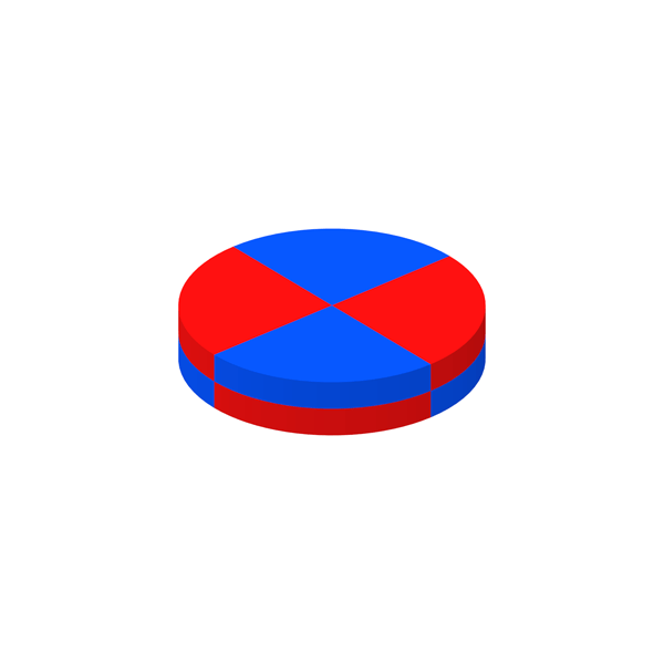
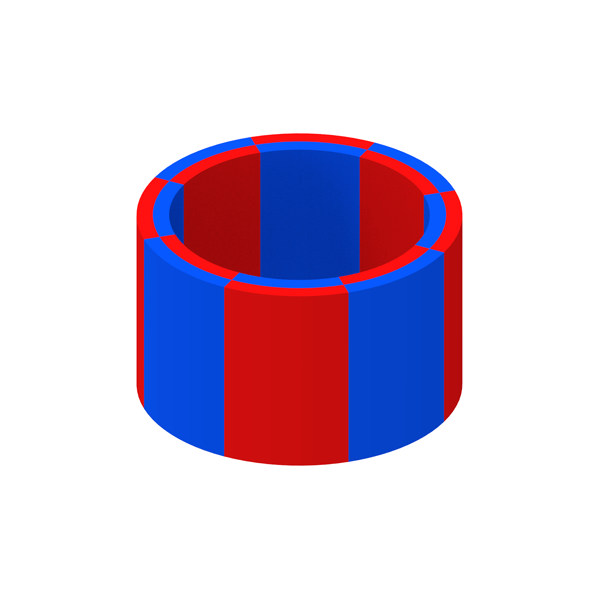
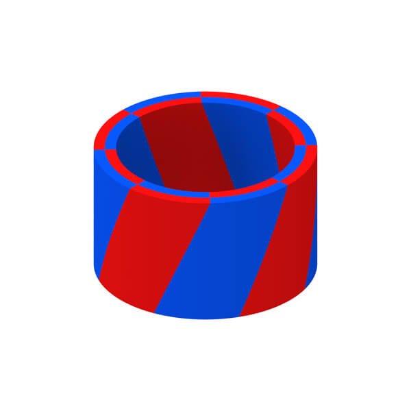
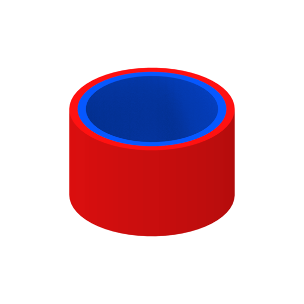
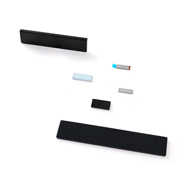
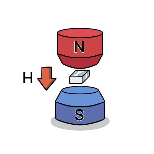
Most permanent magnets need to be magnetized prior to serving in their specific applications. The magnetization process involves applying an external magnetic field along a specified direction to the permanent magnet to achieve saturation. Neodymium magnets possess relatively high coercivity and therefore require a stronger external magnetic field for saturation. Fast impulse magnetization is the preferred method for Neodymium magnets. The impulse magnetization system consists of two main components: the magnetizer and the magnetizing fixture. The magnetizer is a device that stores electrical energy in a capacitor and discharges it into the magnetizing fixture. The magnetizing fixture, also known as a magnetizing coil or magnetizing yoke, is designed to provide the necessary magnetic field strength in the appropriate magnetization patterns or directions. As anisotropic magnets, Neodymium magnets have a preferred direction of magnetization, allowing for various pole configurations as long as they do not conflict with the orientation direction.